Last time, we got a window open and awaiting the instructions that will render our hello world program. But before we actually draw anything, we'll need to supply OpenGL with our data by creating objects of various kinds and uploading data into them. Let's go over the objects we'll need to set up:
The pipeline revisited
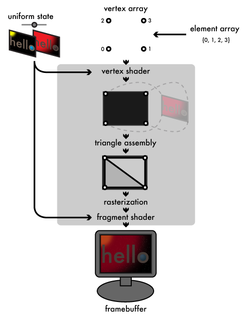
By walking through the graphics pipeline we went over in the first chapter again, this time from the perspective of our "hello world" program, it will be clear what objects we'll need. Starting from the input end, our vertex array will contain four vertices, which the vertex shader will assign to the corners of the window. The element array will compose these four vertices into a two-triangle strip, making a solid rectangle that covers the window. We will build a couple of small buffer objects to hold both of these arrays in GPU memory. Our uniform state will consist of our two "hello" images and the fade factor used to blend them. Each of those images will need its own texture object. In addition to mapping our vertices to the corners of the screen, the vertex shader will assign a set of texture coordinates to each vertex, mapping the vertex to its corresponding corner on the textures. The rasterizer will then interpolate these texture coordinates across the surface of the rectangle so that, finally, our fragment shader can sample the two textures and blend them together using the fade factor. To plug the shaders into OpenGL, we'll create a program object to link together the vertex and fragment shader objects. In this article, we'll set up the buffer and texture objects; next time, we'll work on the shaders.
OpenGL C types
OpenGL defines its own set of GL* typedefs that mirrors the standard menagerie of C types: GLubyte, GLbyte, GLushort, GLshort, GLuint, GLint, GLfloat, and GLdouble alias their corresponding C types as you would expect. On top of this basic set of types, OpenGL provides some additional typedefs with more semantic meaning:
- GLchar*, used by functions that handle strings and expect pointers to null-terminated, ASCII strings
- GLclampf and GLclampd, typedefs for GLfloat and GLdouble used when values are expected to be in the range zero to one
- GLsizei, an integer typedef suitable for holding the size of a memory buffer, akin to the standard C library's size_t
- GLboolean, a typedef for GLbyte intended to contain a GL_TRUE or GL_FALSE value, similar to C++ or C99's bool
- GLenum, a typedef of GLuint intended to contain a predefined GL_* constant
- GLbitfield, another GLuint typedef intended to contain the bitwise-or of one or more GL_*_BIT masks
Storing our resources
static struct {
    GLuint vertex_buffer, element_buffer;
    GLuint textures[2];

    /* fields for shader objects ... */
} g_resources;
A global struct variable like the g_resources struct here is the easiest way to share data between our initialization code and our GLUT callbacks. OpenGL uses opaque GLuint values for object handles. Our g_resources struct contains two GLuint fields we'll use to hold the names of our vertex and element array buffer objects, and a two-element array of GLuints for our two texture objects. We'll add more fields to hold our shader objects when we construct them in the next article.
OpenGL's convention for manipulating objects is a bit unusual. You create objects by generating one or more object names using a glGen*s function (such as glGenBuffers or glGenTextures). As mentioned above, these names are opaque GLuint values. Any data owned or associated with the object is managed internally by OpenGL. That part's fairly typical. How you use the name is the unusual part: to actually manipulate an object, you first bind its name to an OpenGL-defined target by calling the corresponding glBind* function (glBindBuffer or glBindTexture). You then provide the target as an argument to the OpenGL calls that set properties on or upload data into the bound object. Target bindings also affect related OpenGL calls that don't explicitly take the target as a parameter, as we'll see when we discuss rendering. For now, let's see how this pattern plays out when constructing buffer objects:
Buffer objects
static GLuint make_buffer(
    GLenum target,
    const void *buffer_data,
    GLsizei buffer_size
) {
    GLuint buffer;
    glGenBuffers(1, &buffer);
    glBindBuffer(target, buffer);
    glBufferData(target, buffer_size, buffer_data, GL_STATIC_DRAW);
    return buffer;
}
Buffer objects are handles to OpenGL-managed memory. Among other things, they are used to store vertex arrays (using the GL_ARRAY_BUFFER target) and element arrays (using the GL_ELEMENT_ARRAY_BUFFER target). When you allocate a buffer with glBufferData, you supply a usage hint that indicates how often you intend to access and change the data in the buffer, and OpenGL decides the best place in CPU or GPU memory to store its data based on that hint. The hint does not actually constrain how the buffer gets used, but using buffers against their hinted usage will lead to poor performance. For our program, we have constant vertex and element arrays that never need to change, so we give glBufferData the GL_STATIC_DRAW hint. The STATIC part indicates that we don't ever intend to change the data. Buffers can also be hinted either DYNAMIC, which indicates we intend to write into the buffer frequently, or STREAM, which indicates we intend to regularly replace the entire contents of the buffer. The DRAW part indicates that we intend the buffer to be read from only by the GPU. The alternatives to DRAW are READ, which indicates a buffer which will be primarily read back by the CPU, and COPY, which indicates that the buffer will be a conduit between the CPU and GPU and that neither should be given preference. Vertex and element array buffers will almost always use a GL_*_DRAW hint.
static const GLfloat g_vertex_buffer_data[] = {
    -1.0f, -1.0f,
     1.0f, -1.0f,
    -1.0f,  1.0f,
     1.0f,  1.0f
};
static const GLushort g_element_buffer_data[] = { 0, 1, 2, 3 };

glBufferData sees your source data much as memcpy does: just a dumb stream of bytes. We don't tell OpenGL the structure of our arrays until we actually render from them. This allows buffers to store vertex attributes and other data in almost any format, or to feed the same data in different ways to different render jobs. In our case, we just specify the corners of our rectangle as a set of four two-component vectors. Our element array is also simple, an array of GLushorts indexing the four vertex elements in order so that they can be assembled as a rectangular triangle strip. In desktop OpenGL, an element array can consist of 8-bit GLubyte, 16-bit GLushort, or 32-bit GLuint indices; for OpenGL ES, only GLubyte or GLushort can be used. We now fill in our make_resources with calls to make_buffer that allocate and fill our buffers as follows:
static int make_resources(void)
{
    g_resources.vertex_buffer = make_buffer(
        GL_ARRAY_BUFFER,
        g_vertex_buffer_data,
        sizeof(g_vertex_buffer_data)
    );
    g_resources.element_buffer = make_buffer(
        GL_ELEMENT_ARRAY_BUFFER,
        g_element_buffer_data,
        sizeof(g_element_buffer_data)
    );
    /* make textures and shaders ... */
}
Texture objects
static GLuint make_texture(const char *filename)
{
    GLuint texture;
    int width, height;
    void *pixels = read_tga(filename, &width, &height);

    if (!pixels)
        return 0;
As I mentioned in the last article, I'm using the TGA format to store our "hello world" images. I won't waste time going over the parsing code here; it's in util.c in the Github repo if you want to see it. TGA's pixel data is stored as a flat, packed, uncompressed array of three-byte RGB pixels (actually stored in BGR order), with the pixels ordered starting from the bottom left of the image and working rightward and upward from there. This format is perfect for feeding into OpenGL textures, as we'll see shortly. If reading the image file fails, we return zero, which is the "null object" name that will never be used by a real OpenGL object.
    glGenTextures(1, &texture);
    glBindTexture(GL_TEXTURE_2D, texture);
Texture objects provide handles to structured arrays of GPU memory specialized for storing texture data. OpenGL supports several types of textures, each with its own texture target, including 1d (GL_TEXTURE_1D), 2d (GL_TEXTURE_2D), and 3d (GL_TEXTURE_3D) textures. There are also some more specialized texture types we might run into later. 2d textures are by far the most common kind. Here we generate and bind a GL_TEXTURE_2D for one of our images. Texture objects are distinct from buffer objects, because the GPU handles texture memory very differently from buffer memory:
Texture sampling and texture parameters
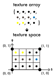
Whereas the vertex array is fed to the vertex shader one element at a time, and there's no way for any execution of the vertex shader to access other elements, a texture makes its entire contents available to any invocation of either the vertex or fragment shaders. Shaders sample the texture at one or more floating-point texture coordinates. The elements of the texture array are distributed evenly into texture space, a square spanning the coordinates (0, 0) to (1, 1) (or a line segment spanning 0–1 for 1d textures, or a cube spanning (0, 0, 0)–(1, 1, 1) for 3d textures). To distinguish from the x, y, z coordinates of object space, OpenGL labels the axes of texture space s, t, and r. The texture space square is split evenly along these axes into rectangular cells, corresponding to the width and height of the original array. The cell bordering (0, 0) maps to the first element of the texture array, and subsequent elements get distributed to cells rightward and upward across the s and t axes. Sampling the texture at the center of one of these cells gives the corresponding element from the texture array.
Note that the t axis can be thought of as increasing either upward or downward (or in any direction, really), depending on the representation of the underlying array. The other axes of texture space are similarly arbitrary. Since TGA images store their pixels left-to-right and bottom-to-top, that's how I'm depicting the axes here.
    glTexParameteri(GL_TEXTURE_2D, GL_TEXTURE_MIN_FILTER, GL_LINEAR);
    glTexParameteri(GL_TEXTURE_2D, GL_TEXTURE_MAG_FILTER, GL_LINEAR);
    glTexParameteri(GL_TEXTURE_2D, GL_TEXTURE_WRAP_S,     GL_CLAMP_TO_EDGE);
    glTexParameteri(GL_TEXTURE_2D, GL_TEXTURE_WRAP_T,     GL_CLAMP_TO_EDGE);

How sampling behaves when a texture is sampled between the centers of texture cells, or at coordinates outside of the zero-to-one range, is controlled by texture parameters, set by the glTexParameteri function. The parameters GL_TEXTURE_MIN_FILTER and GL_TEXTURE_MAG_FILTER control how in-between sample points are treated when the texture is sampled at a resolution lower and higher than its native resolution, respectively. We set them to GL_LINEAR to tell the GPU to use linear interpolation to smoothly blend the four elements closest to the sample point. If the user resizes our window, the texture image will then scale smoothly. Setting the filters to GL_NEAREST would tell the GPU to return the texture element closest to the sample point, leading to blocky, pixelated scaling.
The GL_TEXTURE_WRAP_S and GL_TEXTURE_WRAP_T parameters control how coordinates beyond the zero-to-one range on their respective axes are treated; in our case, we don't plan to sample outside that range, so we use GL_CLAMP_TO_EDGE, which clamps coordinates below zero to zero, and above one to one. A wrap value of GL_WRAP for one or both axes would cause the texture image to be repeated infinitely through texture space along the wrapped axes.
Describing it in abstract, texture sampling might sound like just extremely convoluted 2d array indexing. It will make more sense if we look at how our fragment shader will wind up sampling the texture:
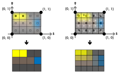
In our vertex shader, we'll assign the corners of the texture space square to our rectangle's vertices. When the rasterized size of the rectangle matches the size of the texture (that is, when our window is the same size as the image), the centers of the fragments (the crosses in the figure) will line up with the centers of our texture cells (the circles), and the fragment shader will wind up sampling the image pixel-for-pixel, as you see on the left side. If the rectangle's rasterized size doesn't match the texture, each fragment will wind up sampling between the centers of our texture cells, and the linear filtering will ensure we get a smooth gradient between the texture elements, as the right side demonstrates.
Allocating textures
    glTexImage2D(
        GL_TEXTURE_2D, 0,           /* target, level of detail */
        GL_RGB8,                    /* internal format */
        width, height, 0,           /* width, height, border */
        GL_BGR, GL_UNSIGNED_BYTE,   /* external format, type */
        pixels                      /* pixels */
    );
    free(pixels);
    return texture;
}
The glTexImage2D (or -1D or -3D) function allocates memory for a texture. Textures can have multiple levels of detail, sampling from a hierarchy of progressively smaller "mipmaps" when sampled at lower resolutions, but in our case we only supply the base level zero. Unlike glBufferData, glTexImage2D expects all of the format information for the allocated memory to be presented up front. The internal format tells the GPU how many color components to store per texture element and at what precision. OpenGL supports all sorts of different image formats; I'll only mention what we use here. Our TGA files use 24-bit RGB pixels, in other words, they sport three 8-bit components per pixel. This corresponds to the GL_RGB8 internal format. The width and height count the number of texture elements along the s and t axes. (The border argument is a relic and should always be zero.) The external format and type declare the component order and type of our pixels argument, which points to width × height packed texture elements of the specified format. TGA stores its unsigned byte-sized pixel components in BGR order, so we use GL_BGR for the external format and GL_UNSIGNED_BYTE for the component type.
Let's add some make_texture calls to our make_resources function to create our texture objects:
static int make_resources(void)
{
    /* ... make buffers */
    g_resources.textures[0] = make_texture("hello1.tga");
    g_resources.textures[1] = make_texture("hello2.tga");

    if (g_resources.textures[0] == 0 || g_resources.textures[1] == 0)
        return 0;
    /* make shaders ... */
}
Next time, shaders
We now have our vertex and image data prepped and ready to launch through the graphics pipeline. The next step is to write the shaders that will steer that data through the GPU and land it on the screen. That's what we'll look at in the next part of this chapter.