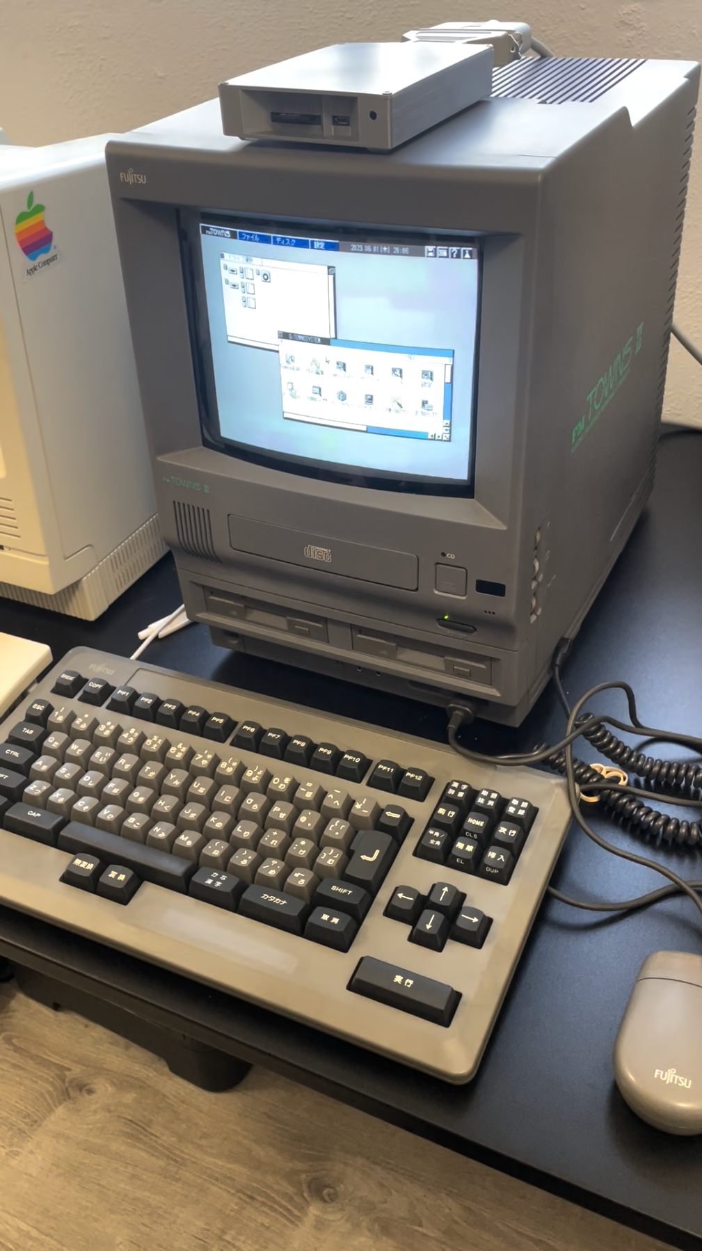
The previous owner of my FM TOWNS UX20 thoughtfully removed the CMOS battery from the computer to keep it from exploding and damaging the electronics inside, but unfortunately, TOWNS OS uses the CMOS settings to remember whether you have a hard drive and what drive letter(s) to use for it, so without a battery, you have to reconfigure the hard drive every time you power up. So I opened it up to put a new battery inside. There isn't a lot of documentation on the English Internet about taking these machines apart, so I'll walk through how I did it here. Like anything with a CRT in it, be careful about extremely high voltages that may still be charged inside!
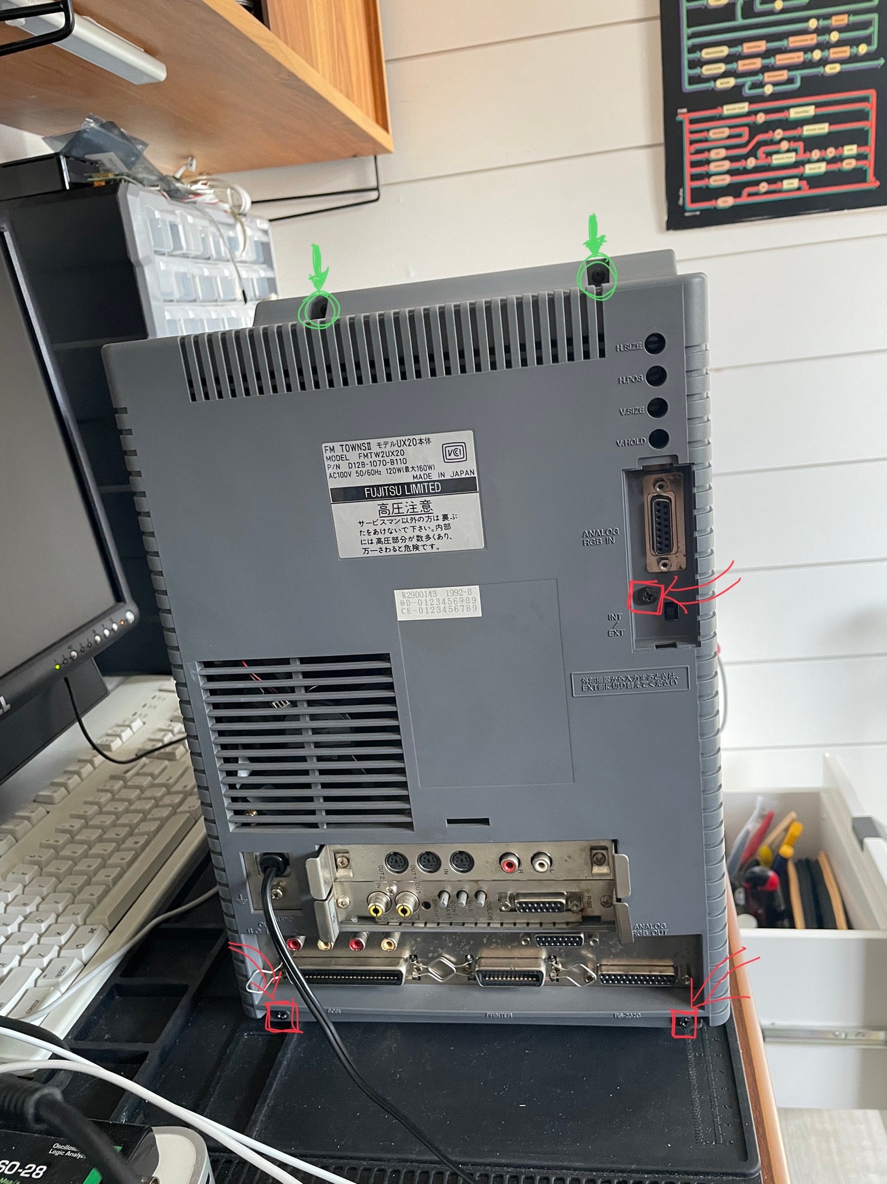
Five Philips head screws hold the case to the back of the computer. One of them is inside the door that protects the RGB in port. Two screws near the bottom and the one inside the door (marked in red ⇒▢) are interchangeable, but the two screws on the top (marked in green ➦◯) are different, so keep them sorted after removing them. If there are expansion cards in the expansion slots, remove those too, since they mount to the back case.
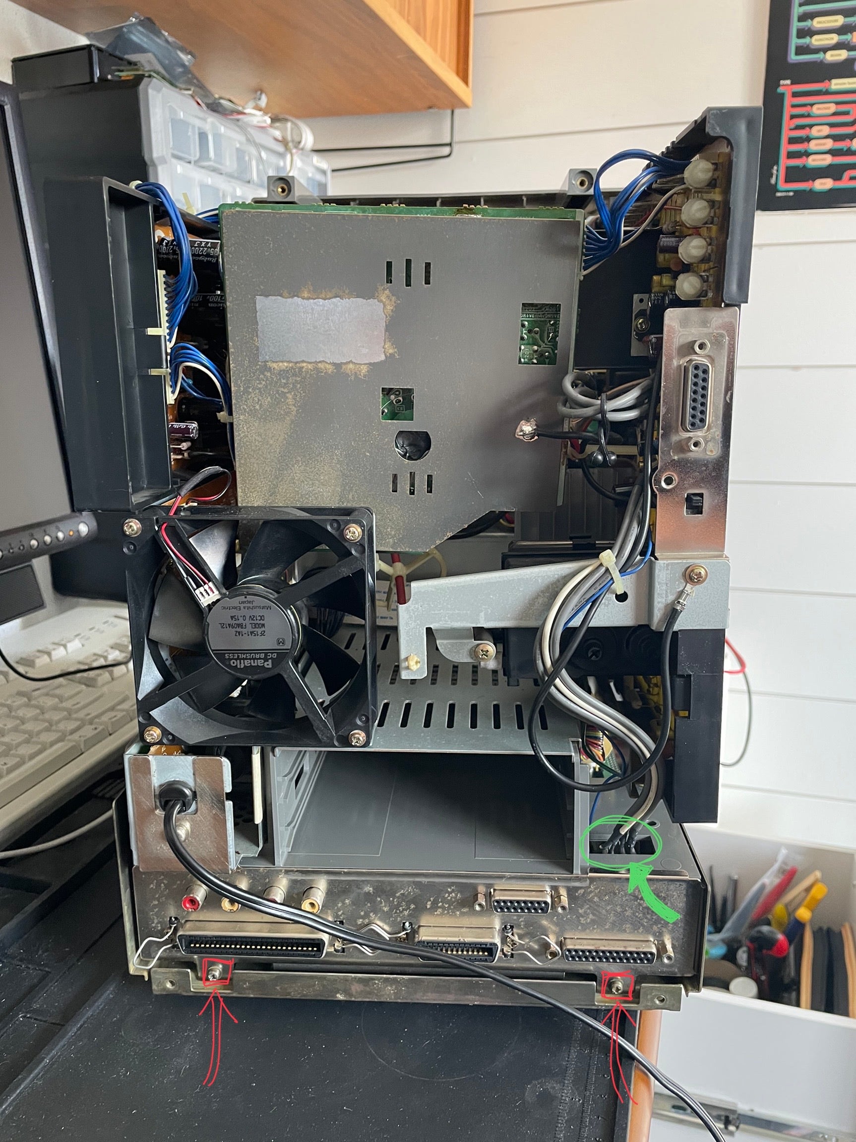
Sort of like a compact Mac, there's the CRT tube and high-voltage analog electronics in the top half of the case, and lower-voltage digital electronics in the bottom. Thankfully, we only (mostly) need to look at that lower half today. The computer part of the machine, including the logic board, video board, and floppy drives, slides out from the back after being detached. To do that, there are two screws (marked in red ⇒▢) to remove from the bottom of the metal shielding, as well as several connectors spread across the various sides of the machine. The first one is the connector with several thick gray and white wires and one thin blue wire (marked in green ➦◯). When reconnecting this connector later, the blue wire goes toward the inside of the machine.
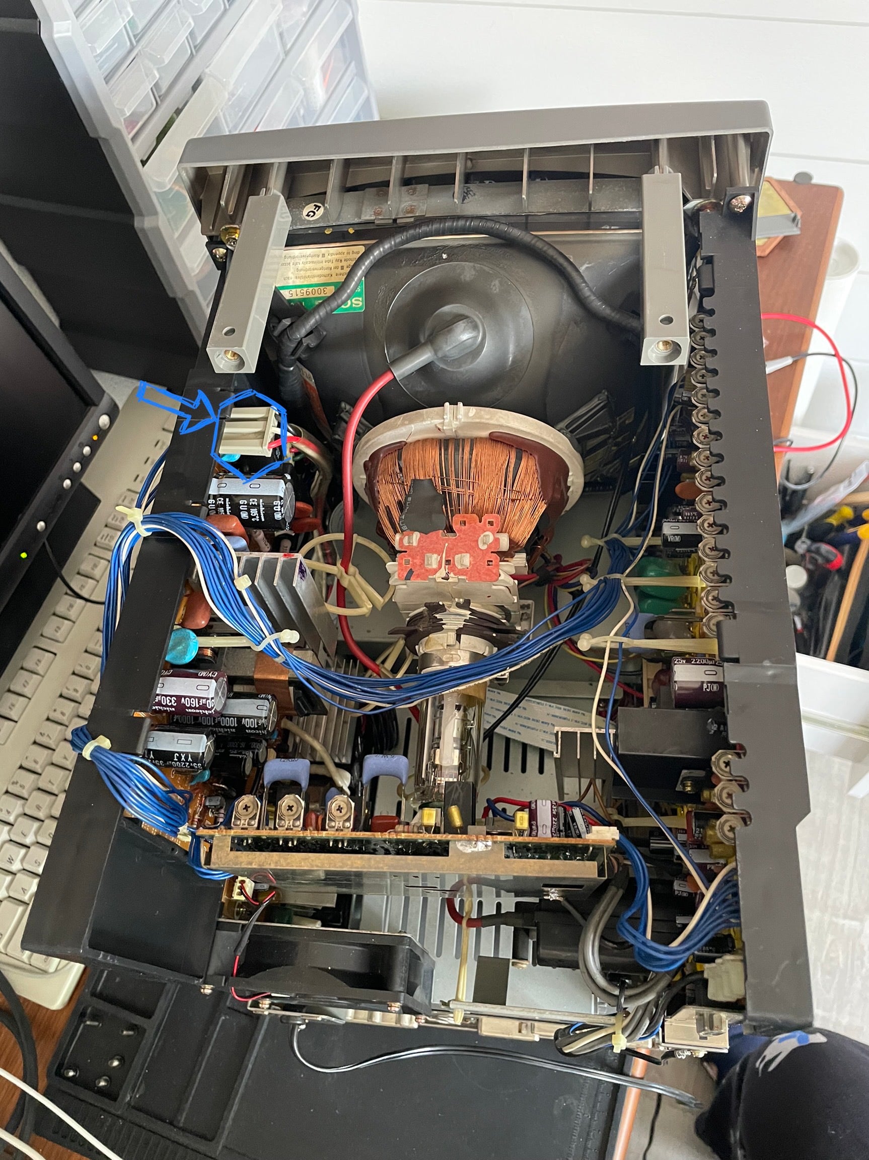
Our one excursion into the high-voltage top half is to remove this one power connector (marked in blue ➪⬡). Do it very slowly and carefully, since it hugs the pins very tightly, and the plastic mounts for the analog boards are very flimsy. You also don't want to bang it into the CRT deflection coils right behind it when it comes loose…
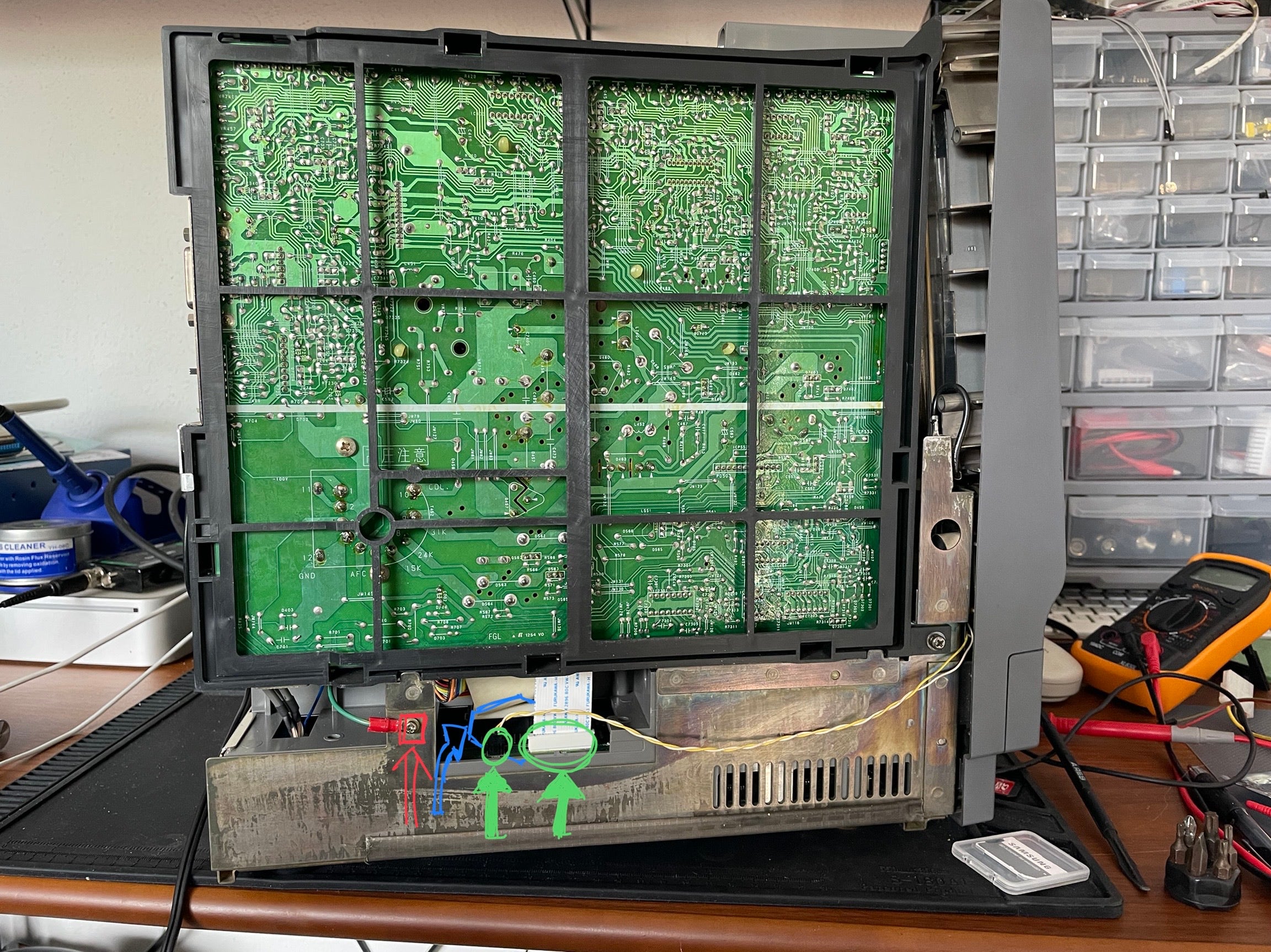
The remaining connectors to remove are on the left side of the machine. The ground lug (marked in red ⇒▢) needs to be unscrewed. There are three connectors accessible in the space to the right of it: a two-wire JST connector, a ribbon cable in a ZIF socket (marked in green ➦◯), and behind them an IDC connector (marked in blue ➪⬡). The IDC connector has some slack, so you can pull the computer out a bit to get better access to it from outside. Later when reconnecting these cables, the JST and IDC connectors are keyed, but the ribbon cable is not, so remember what way it's facing; in my case, the printed side was facing toward the outside of the computer.
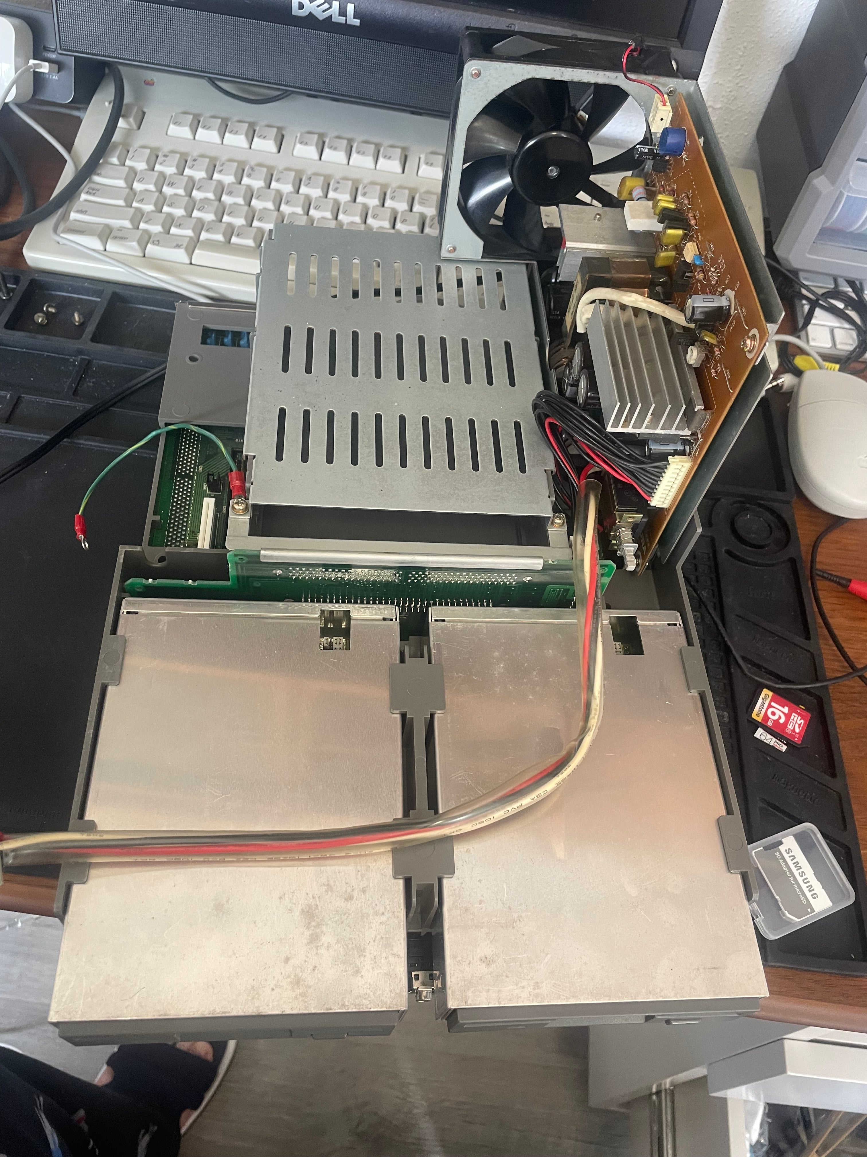
With all those connectors removed, the computer and power supply should pull out the back. The CMOS battery compartment is underneath the second floppy drive on the right.
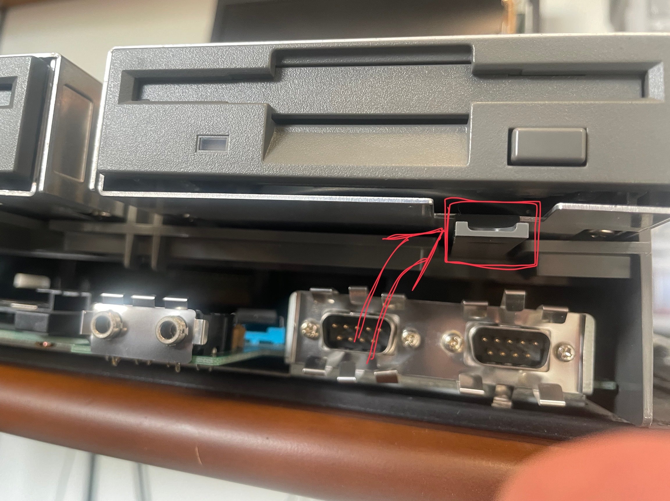
The floppy drives pull right out from the backplane behind them. You just need to push down the plastic tab underneath one (marked in red ⇒▢) to release it.
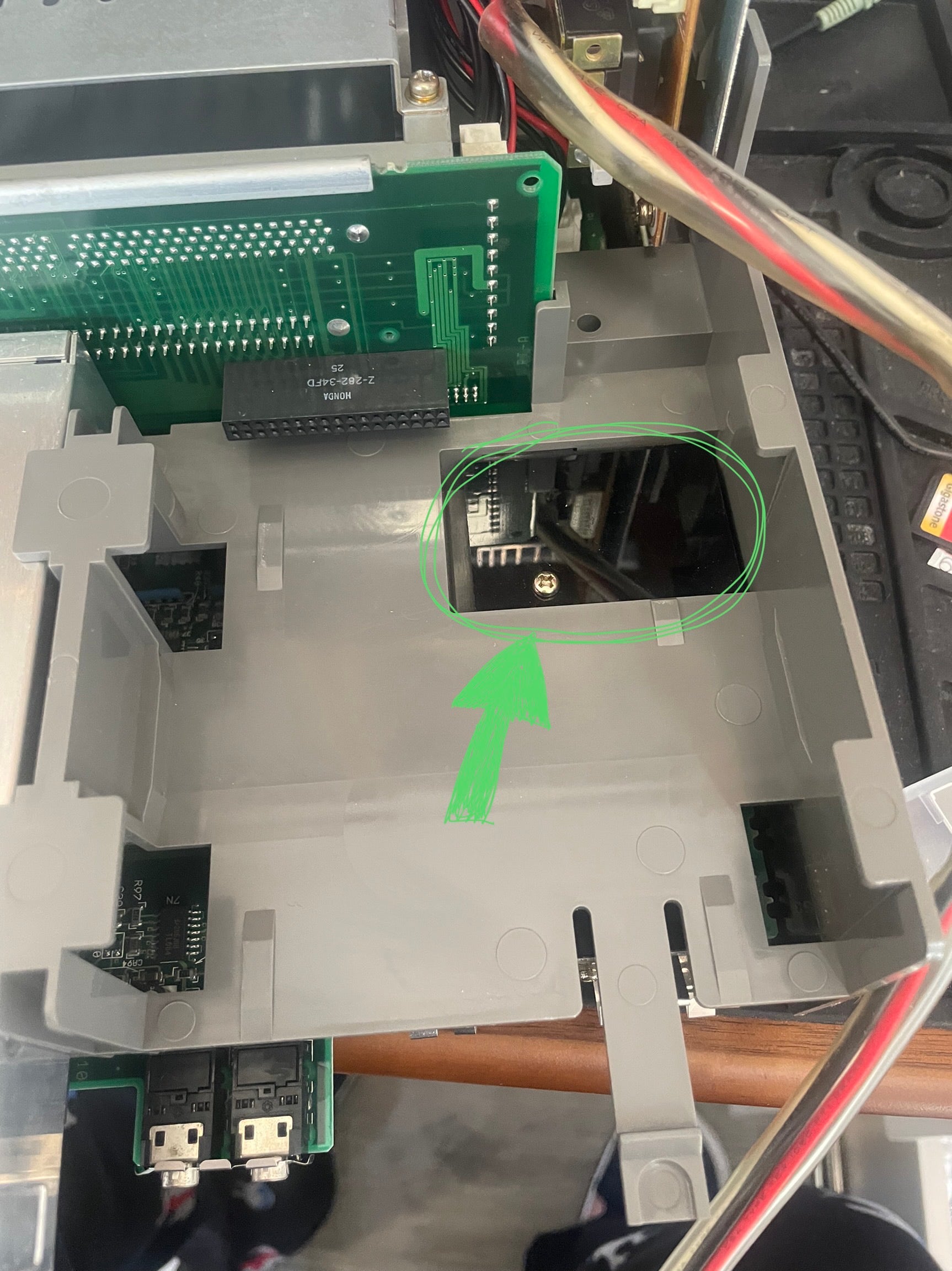
Underneath, a reflective black plastic door protects the battery compartment. Removing the one screw frees it.
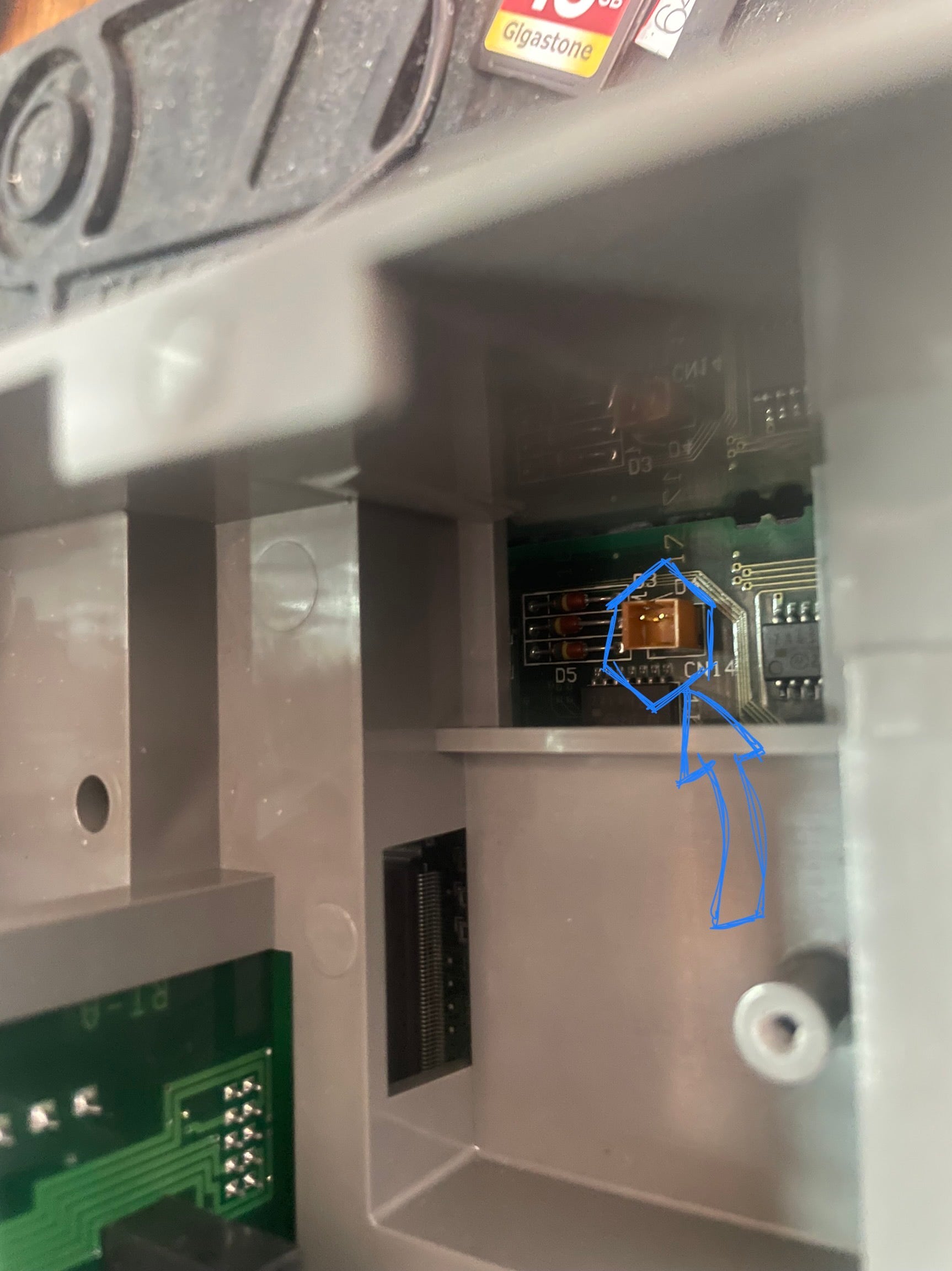
At last, here is the connector for the CMOS battery, silkscreened CN14 on the board (marked in blue ➪⬡). The connector is a JST PH style connector.
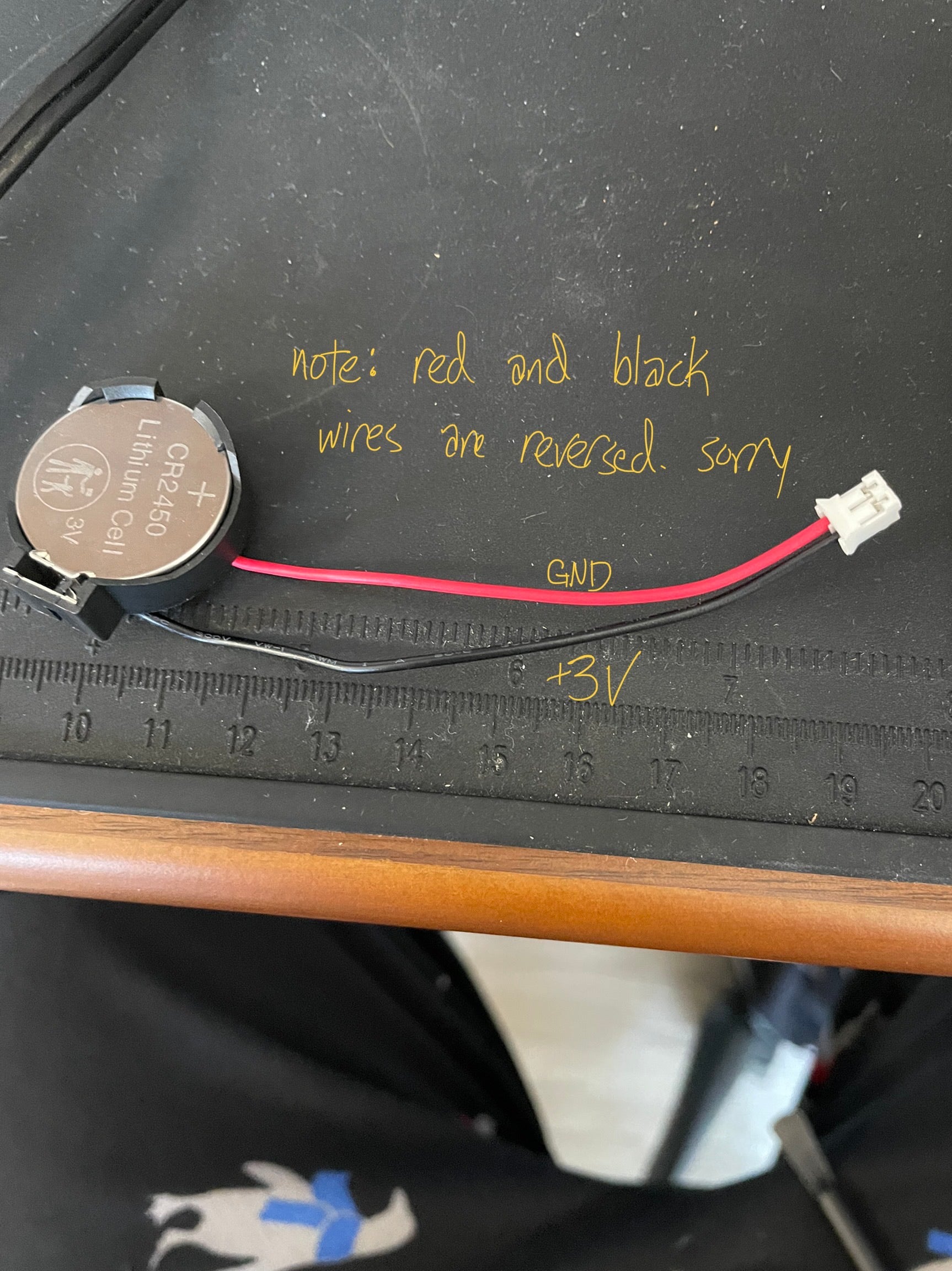
From what pictures I could find online, the original CMOS batteries Fujitsu used were CR2450s with welded leads. I don't like to solder batteries if I can avoid it, so I got a socketed battery holder instead. I had a wireset with a JST connector already that I'd taken from another battery, so I reused it here. (As noted in the picture, the red and black wires are reversed from the pinout the FM TOWNS wants, so the black wire is carrying +3V and red is ground.)
With that done, and everything put back together, I can actually install TOWNS OS and some software on the hard drive!